Navigation


Transparent Front Cover PC0108 Installation Tutorial

PC0108 Installation Tutorial

 Have questions? Click to view "Installation FAQ"

  • Precautions

Replacing the cover is a difficult and time-consuming job, estimated to take 3 to 5 hours. We strongly recommend that you seek the help of a professional repairer. Regarding the change of the whole machine maintenance policy caused by the disassembly, please refer to the information officially released by VALVE.

As an extra precaution, Valve recommends entering the BIOS to put the Steam Deck in battery storage mode before starting internal repairs. If you have installed a Micro SD card, please remove it before disassembly.

Before starting the disassembly, make sure the Steam Deck battery has dropped below 25%, is fully powered off, and disconnected all connected cables. Please follow the anti-static safety regulations during operation, and keep the removed original accessories properly. Be aware that accidentally damaging a live Lithium-ion battery can result in serious hazards.

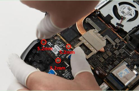
During repairs, please manage the screws properly to ensure they are correctly replaced to avoid damage to the Steam Deck. During the installation process, please note that the "L" logo should be on your right and the "R" logo should be on your left to prevent installation errors.

Note that the order of the video tutorials and this document may be slightly different, they provide two possible disassembly sequences, both of which will ensure proper removal and installation of the device. You can choose a reference according to your actual situation.

  • Disassembly Steps
1. Tool Inspection
Please make sure that all disassembly tools are ready, the package includes:
        screwdriver
        spare screw
        stick
        Adhesive Cutting Sheet
        sucker
        Screen Adhesive
        Storage Box
        Tweezers
        Anti-static gloves

The following are not included in the package and need to be prepared by yourself:
        Hair dryer (or other heating products, mainly used to remove the screen)
If you have made the above preparations, please wear anti-static finger cots or anti-static gloves, and start the following replacement steps.
2. Accessories and Tool Descriptions
About the screwdriver:
The screwdriver has an extra replaceable bit, it's inside the screwdriver, you need to pull off the cap on the top of the screwdriver and pour the other bit out of it.
When replacing the cutter head, first unscrew the ring buckle at the front end, pull out the old cutter head, then install the new cutter head and tighten the buckle.
 In the subsequent disassembly and installation steps, all the screws marked with red circles use 1# bit, and the screws marked with green circle use 2# bit.

About the screw:
The screws removed from the machine can be placed in the screw box we donated. Each box in the screw box has a sticker marking the size of the screw, and each box is placed with a screw of the same specification as a gift from us for spare.
    Screw specification parameters introduction:
    For example: 3.4mm CM1.6 * 3.0-D3.0 * 0.5mm
    "3.4mm" : refers to the overall height of the screw.
    "CM": flat head machine teeth.
    "CB": flat self-tapping thread.
    "1.6" : is the thread diameter.
    "3.0" : is the thread length.
    "D3.0" : is the nut diameter.
    "0.5" : is the nut thickness.
If you accidentally lose all your screws, you can purchase replacements by referring to the screw specifications used in this tutorial.
During the installation process of the gaming console, each screw in every position only needs to be gently tightened into place, ensuring that the components are securely fastened. Avoid using excessive force when turning the screws. The gaming console's outer shell is made of plastic material, making it very fragile when dealing with screws. In addition, the gaming console's PCB circuit board is also very delicate. Over-tightening can cause damage to them.
About blister trays:
There is a blister tray and parts location map on the lower layer . The parts removed during the disassembly process can be placed in the corresponding position in the tray to avoid loss during the disassembly process or during installation.
3. Remove the Back Cover
Use a 1# head screwdriver to remove the 8 screws on the back cover, put the 4 shorter ones in the 5.8mm screw box, and put the longer 4 screws in the 9.5mm screw box, use the disassembly crowbar to open and remove the game console the back cover.
4. Remove the Shield
Uncover the sticker covering the protective plate, use a 1# head screwdriver to remove the 3 screws on the protective plate, one of which is 3.4mm, and the other two are 3.7mm, and then take off the protective plate.
5. Disconnect the Power Cable
Pinch the cable or use the flat end of a spudger to push out the plug to completely disconnect the battery cable.
6. Disconnect the MCB Cable
Disconnect all the cables on the left and right MCB in the figure below.
During the operation, you need to open the lock of the ZIF cable first, and then pull the plastic piece on the cable to pull out the plug.
When prying the cable of the touchpad vibration motor, be sure to use the tip of the prying rod to lift the cable itself, not its casing.
There are 7 cables on the ‘R’ board that need to be disconnected, and 6 cables on the ‘L’ board that need to be disconnected.
7. Disconnect the Display and Fan Cables , the Microphone Cable
Pinch the fan cable and pull out the plug to completely disconnect the fan cable.
Open the lock on the ZIF interface, and then pull the plastic sheet on the cable to pull out the plug of the display cable.
Use the flat end of a spudger to open the white lock of the ZIF seat of the display cable, then gently lift the plastic sheet of the microphone cable, and pull out the plug.
8. Remove the motherboard screws
Use a 1# head screwdriver to remove the 3 screws that fix the motherboard, they are 3.7mm.
9. Flip Over the Main Board and Remove the Display Cable
Uncover the heat sink sticker.
Flip the main board and radiator 180° around the lower right corner of the main board to expose the display cable at the bottom of the main board.
When turning it over, pay attention that the speaker and FPC linked in the lower right corner of the main board are still connected, do not pull it too far to prevent damage.
Tear off the sticker covering the cable, pick the lock on the ZIF seat, and remove the display cable.
Flip the main board back to its original position, use a 1# blade screwdriver to install the 3 screws that fix the main board, they are 3.7mm.
10. Remove trigger
Use the flat end of a crowbar to reach the buckle on the inner side of the trigger button, pick the inner buckle, carefully move the buckle on the outer side of the trigger button, and loosen the buckles on both sides to remove the trigger button.
Take off the trigger key, be careful not to remove the spring attached to the trigger key, be careful not to lose the spring.
Use the same method to remove the triggers on the left and right sides in turn.
11.Remove Trigger Bracket
Use a 1# head screwdriver to unscrew the 3 screws that fix the trigger bracket, they are 5.2mm, and remove the trigger bracket.
Use the same method to remove the trigger brackets on the left and right sides in turn.
 
12. Remove Joystick
Use a 1# head screwdriver to remove the 3 screws on the rocker plate, they are 5.2mm, and take off the rocker.
Use the same method to remove the left and right joysticks in turn.
13. Remove the Button MCB 
Use a 1# head screwdriver to remove the 4 screws on the button MCB, including 3 screws of 5.2mm and 1 screw of 3.9mm, and remove the button MCB.
Use the same method to remove the left and right button MCB in sequence.
14. Remove the Touchpad MCB
Use a 1# head screwdriver to remove the 4 screws that fix the touchpad MCB, they are 4.7mm, and remove the touchpad MCB.
Use the same method to remove the left and right touchpad MCB in sequence.


15. Remove Steam Key and Quick Access Key
Remove the conductive glue and buttons of the Steam button and the quick access button insequence.
16. Remove the shoulder key Assembly
Use 1# head screwdriver to remove the 2 screws fixing the shoulder key assembly, they are
5.2mm, and take off the shoulder key assembly.
Note: The edge of the shoulder key assembly is just stuck under the buckle of the cover. When removing it , you can lift it from the top first, and then slowly remove the shoulder key assembly.
Use the same method to remove the left and right shoulder key assemblies in turn.
17. Remove Conductive Glue, Action Keys and Function Keys
Remove the cross key conductive glue and the action button conductive glue in turn, and be careful not to lose the buttons when removing the conductive glue.
Remove the cross key, action key and left and right function keys in turn.

18. Remove Screen

Use a hair dryer or other heating device to heat the surrounding area of the screen.
Be careful not to keep heating the same place all the time, to avoid overheating the screen, the display screen and battery are easily damaged due to overheating.
Note: According to our experience, if you use a hair dryer with a power of 1 KW and move it around the screen 2-3 cm away from the screen, it will take about 50-80 seconds to heat up.
Fix the suction cup on the upper left corner of the screen, as close as possible to the edge of the screen, and press down to generate suction.
Use a strong and steady force to slowly pull the suction cup upwards, pay attention not to be too large, until there is a gap between the display and the frame, then insert the adhesive backed cutting sheet, the depth should not exceed 3mm
Note: When using a cutting sheet, it is recommended to start cutting from the lower left corner and move slowly. Do not insert the cutting sheet too deep to avoid damaging the screen cable.

Cut the back glue along the screen circle, after the back glue is cut, carefully grab the left edge of the screen and lift up the screen until the screen is completely free from the frame.
When removing the suction cup from the screen, you can slightly pry the edge of the suction cup, as long as there is a small gap, you can easily remove the suction cup, avoid using brute force to pull the suction cup and the screen.
19. Clean the Screen Adhesive
Use glue remover or alcohol (>90%) to remove any remaining residue. wipe in one direction with a lint-free cloth or coffee filter until all adhesive residue is gone.
Be careful not to use any sharp objects to scrape the residual adhesive on the screen, such operations will damage the screen coating.
For easy cleaning, you can heat up the adhesive. 
This step may take a considerable amount of time, so please be patient while performing it.
Although alcohols are generally safe for use in electronics, they can dissolve some foam adhesives. Pay attention to controlling the amount used when cleaning, and do not use too much.
Allow any remaining alcohol to evaporate completely before reassembling the device.

20. Remove Speaker
Insert the flat end of the crowbar between the speaker and the frame, and use the crowbar
to pry up the speaker. If the adhesive is very tight, you can use a hair dryer to heat and soften the adhesive before taking out the speaker.
Use the same method to take out the speakers on the left and right sides in turn.


21.Remove Middle Frame
Use a 2# head screwdriver to remove the 6 screws on the front of the middle frame, they are 2.3mm.

Use a 1# head screwdriver to remove the 4 screws on the back of the middle frame, they are 5.2mm.
Remove the middle frame from the rear side.

22. Remove Trackpad
Use a 1# head screwdriver to remove the 4 screws that fix the touchpad, they are 4.7mm.
Use the same method to remove the left and right touchpads in sequence.
Take out the touchpad vertically, be careful not to bend the spring around the touchpad, and make sure it can be placed in the corresponding positioning hole when reinstalling the touchpad.

23. Clean up the Adhesive on the Middle Frame
Use adhesive remover or alcohol (>90%) to remove any remaining residue. wipe in one direction with a lint-free cloth or coffee filter until all adhesive residue is gone.
You can clean it using the same method as cleaning the screen adhesive, or you can use sharper objects to increase the cleaning speed. The middle frame is stronger compared to the screen.


24. Remove Power and Volume Buttons
Use tweezers to remove the volume key and power key.

25. Remove the Microphone Flex Cable
Insert the flat end of a spudger under the microphone flex cable and pry up to separate it from the front panel.
The microphone cable has three places where adhesive is applied and needs to be separated sequentially. If necessary, equipment can be used for heating.
At this point the front panel has been completely separated from other components.
  • Installation Steps
1.Check PC0108
Make sure before installation
The light guide column is not missing
Three dust-proof nets are not missing
Before installation, you can try to place the button in the corresponding button hole to test whether there is interference. The button in a suitable hole can fall freely to the bottom without pressing hard.
If it is confirmed that there is interference in the buttonhole, it may affect the function of the button and the normal use of the machine, please contact our after-sales personnel to replace it for you for free.
2. Install Power and Volume Buttons
Use tweezers to hold the volume button, put the button down from the plastic buckle, and use a pointed crowbar to fix the button in place.
Use tweezers to hold the power button, and put the plastic strips on both sides of the power button from the plastic buckle.
3. Install the Microphone Cable
The middle of the microphone cable , the lower left and the lower right respectively, the small holes on the cable correspond to the pillars on the cover, and press the back glue after alignment.
4. Install the Trackpad
The touchpads on the left and right sides in the corresponding positions. 
Use a 1# head screwdriver to fix the four 4.7mm screws on the touch panel. 
Use the same method to install the left and right touchpads in turn.
5. Install the Middle Frame
Install the middle frame just removed on the cover, aligning with the screw holes on the cover when installing.
Note: Do not press the microphone cable when installing the middle frame. When installing, first align the volume button and power button, and slowly place the middle frame. There is a buckle on the top of the cover. When installing, pay attention to fixing the middle frame in place.
6. Fixed Middle Frame
Use a 1# head screwdriver to install the four 5.2mm screws on the back of the middle frame.
During the installation process, you will find that the 5.2mm screws secure the middle frame to the front cover, while the middle frame is fixed to the back cover by 9.5mm screws. Therefore, you need to avoid tightening the 5.2mm screws too much.
Use a 2# head screwdriver to fix the six 2.3mm screws on the front side of the middle frame.
7. Fixed Speaker
Fix the left and right speakers on the cover respectively, and the original adhesive can be reused.
Note: If you need to replace the adhesive, remember to clean up the original adhesive.
 
8. Paste the Screen Adhesive
The middle frame and the face cover are fixed by screws and also have some snaps. Before pasting the adhesive, make sure these snaps are completely locked, otherwise, it will cause the adhesive to not be flat and the screen cannot be fixed.
Paste the attached new screen adhesive around the middle frame, starting from the top adhesive, and tear off the film on the adhesive after pasting.
Note: Confirm the location of the adhesive before installation, avoid folding the adhesive when pasting, and avoid the adhesive beyond the frame.
There are reserved screw holes and photosensitive components on the back glue, please pay attention to avoid pasting.
If you accidentally paste the wrong adhesive, you can tear it off and install it again.

9. Install screen
Before installation, make sure that the residual adhesive on the screen has been completely cleaned, and a new adhesive has been pasted on the middle frame.
Paste the screen on the front of the middle frame, and note that the position of the cable behind the screen should be the same as the position of the cable opening on the middle frame.
After fixing the position of the screen, you can press slightly along the periphery of the screen to make the adhesive fully fit.
If you find that the screen and the surface of the cover are obviously raised after pasting the screen, you need to remove the screen and re-paste it, and check whether the snap of the cover and the middle frame has lifted the screen, or if your screws are not tightened to the bottom. Of course, you can also take a photo and consult our customer service staff, they will provide you with professional advice.

10. Install the Screen Cable
Flip the machine over, use a 1# head screwdriver to remove the 3 screws that fix the main board, they are 3.7mm.
Expose the display cable interface at the bottom of the main board, install the display cable just removed on the interface, and paste the cable.

Flip the main board back to its original position, use a 1# blade screwdriver to install the 3 screws that fix the main board, they are 3.7mm.
Connect the display cable and fan cable on the main board.

Note: The display cable is very fragile and requires very high precision. Please make sure that the cable is fully inserted into the seat and is in good contact. If you find that the position of the cable is shifted during insertion, please re-operate until the cable is fully inserted. Turn on the power.
 11. Install Action Keys and Cross Keys
Put the ABXY and the cross key in the corresponding position on the cover, each key corresponds to only one position, don't worry about misplacing it.

12. Install Menu and View Keys
Place the view key and menu key in the corresponding positions on the cover.
13. Install Conductive Glue
The cross key and the action key conductive silicone on the corresponding position.

Do not remove the cover after installation.

14. Install the Shoulder Key Assembly
Fix the shoulder key assembly on the corresponding position of the cover, and use a 1# head screwdriver to fix it with two 5.2mm screws.
Because the side of the shoulder key is under the buckle, start from the side when installing, put the side under the buckle, and then fix the space and pillars below.
Note: The fixed arm of the shoulder key assembly is very slender, and the wall of the screw hole at the end is also very small . Do not use too much force when tightening the screws to prevent the screw holes from being damaged.
Use the same method to install the shoulder keys on the left and right sides in turn.
After the installation is complete, you can try to press the shoulder button to ensure that the button can operate normally.

 15. Install Steam Key and Quick Access Key

Install the Steam key and quick access key on the corresponding position on the cover.
Install the Steam button conductive glue and quick access button conductive glue on the button.
The conductive glue of the two buttons is the same, and they can be mixed with each other without affecting the feel and function of the buttons.
Do not remove the cover after installation.

 16. Installing the Touchpad MCB

Place the touchpad MCB on the touchpad, pay attention to the left and right distinctions on the MCB, and pay attention to the direction of the MCB when installing.
Use a 1# head screwdriver to fix the four 4.7mm screws on the touchpad MCB.
Use the same method to install the left and right touchpad MCB in turn.
17. Install the Button MCB
Place the button MCB in the corresponding position, and use a 1# head screwdriver to fix three 5.2mm screws and one 3.9mm screw.
Use the same method to install the left and right button MCB in sequence.
18. Install Rocker Plate
Place the rocker on the corresponding position of the cover. Note that there is a distinction between left and right on the MCB. Since the installation process is reversed, the one marked "L" on the PCB should be on your right hand side, and the one marked "R" should be on the right hand side. On your left hand side, avoid putting it backwards when installing.
Use a 1# head screwdriver and three 5.2mm screws to fix the rocker plate.
Use the same method to fix the left and right rocker plates in sequence.
19. Connect the Cable
Connect all the cables on the left and right MCB in the figure below.
When connecting, use tweezers to clamp the plastic sheet of the cable, push the plug in from the direction parallel to the ZIF interface, and then press the lock on the ZIF interface. During the process, avoid the plug being crooked or not fully pushed in.
When installing the microphone cable, insert the cable downwards into the seat, and then use a tool to press the white seat plug tightly.
When installing the display cable, be sure to confirm that the cable is fully inserted into the seat and that the contact is good. If you find that the position of the cable is shifted during insertion, please do it again.
20. Try to Boot
In order to avoid the need to disassemble the machine again if it is found that the machine cannot be turned on after the subsequent installation, you can connect the power cable and try to turn it on.
Pay attention to avoid touching the MCB as much as possible during the process.
Press the power button to try to turn on the machine, and confirm whether the machine can be turned on normally and display the screen.
Note: In most cases, it needs to be plugged in and activated before it can be turned on.
If the screen cannot be turned on normally, please disconnect the power cable and check whether the installation steps are missing.
If the screen still cannot be turned on after checking again, please stop trying and seek professional help.
If the screen can be turned on normally, please continue to follow the steps below after powering off.
21. Install the Protective Cover
Use a 1# head screwdriver to install the 3 screws on the protective plate, one of which is 3.4mm and the other two are 3.7mm.
Restore the sticker on the protective cover after installation.
When installing, pay attention to the heat dissipation silicone grease inside the protective cover, which is pasted on the inner wall of the protective cover for heat dissipation, and make sure that they are not falling off before installation.
22. Install the Trigger Bracket
Put the trigger bracket on the button MCB, use a 1# blade screwdriver and three 5.2mm screws to fix the trigger bracket.
Use the same method to fix the left and right trigger brackets in sequence.

23. Install the Trigger
After installing the trigger bracket, fix the left and right triggers on the trigger bracket.
When assembling, first fix the spring in the correct position, then assemble from the outer buckle, and then put on the inner buckle . If you hear a "click" when you put the buckle in, it proves that the buckle has been locked.

24. Install the Back Cover, Boot
Put the back cover on, press the buckle firmly to make it close to the front cover, and fix the back cover with four 9.5mm screws and four 5.8mm screws.

Congratulations, you have completed the cover replacement!
  • Board Calibration
Valve Corporation recommends performing this software calibration process after installing new triggers.
Note: Steam Deck stick and trigger calibration may not work properly as of Steam OS version 3.3. This functionality is expected to be restored in a future release.
1. Open the Konsole Console
If you are not already in desktop mode, navigate to Steam Menu → Power and select Switch to Desktop.
If your Steam Deck does not have a keyboard plugged in, you will need to use the on-screen keyboard.
Press the Steam button + X to enable the on-screen keyboard.
Done in a terminal window using Steam OS's console (named Konsole).
From the Search menu, search for and open Konsole.
If necessary, move the Konsole window so that the on-screen keyboard does not cover the window.
2. Start Trigger Calibration
In the Konsole console, enter trigger_cal.
Or you can type trig and press Tab to autocomplete.
Press enter.
3. Perform Trigger Calibration
The software will first calibrate the rest position when the trigger is not pressed.
Make sure both triggers are not pressed, press enter.
The software will now calibrate where the trigger is fully depressed.
Move the pointer out of the Konsole console window and click on the blank desktop area to ensure that the Konsole console is activated.
Depress each trigger lightly until it bottoms out.
Do not apply too much force, or the trigger may be miscalibrated.
Click on the Konsole console window to reactivate it, press enter.
 
You're done! Your trigger is now calibrated and the Konsole console should display "Trigger calibration successful."